Experimenting with the Microduino MicroWRT Core (I)
We are experimenting with three MicroWRT Core boards that Jason from Microduino™ kindly sent us some days ago.
The MicroWRT is a small and cheap development board based on the MediaTek MT7620A SoC (which integrates Ethernet networking and 2.4 GHz WiFi 2T2R), with 64 MB of RAM and 16 MB of flash storage. It is fully supported by the currently latest OpenWrt 15.05 Chaos Calmer release and, since recently, by the qMp 3.2 Clearance stable release.
 The device consists of a board with the SoC, a µUSB port, two buttons, two antenna connectors and 52 accessible pins. These pins can be used to stack several boards that provide diverse functionalities (Ethernet, USB, mPCI-E, etc.) and to even to a series of Microduino™ board (which are Arduino-compatible).
Its powerful CPU, its small size, the number of extension boards that can be attached to the MicroWRT Core and its interaction capabilities with the Microduino™ range of boards make it a very interesting option to build a mesh network with sensors, actuators, etc. with up to several Mb/s of throughput.
This article covers the installation and configuration of qMp in three MicroWRT Core devices that create a small mesh and exchange data from a sensor between them.
Installing qMp
The MicroWRT Core is shipped with PandoraBox, a sort of Chinese customisation of OpenWrt -anyway, OpenWrt after all-. Therefore, flashing qMp or upgrading to a newer OpenWrt version is very easy and can be done using the node's LuCI web interface.
First, download the appropriate qMp precompiled binary firmware from the Download page, or compile it with your preferred options. At the time of writing this page, the latest stable qMp firmware for this device is available here.
Connect the device to your computer, either via Ethernet or WiFi. The factory firmware puts the wireless interface in access point and creates up an open wireless network named PandoraBox_XXXX which you can use to flash the device, but it is recommended to do it via cable. Open the device's web interface with your browser and go to the System menu => Backup / Flash firmware. Use the form to select the qMp firmware file (make sure you don't keep the previous settings) and upload it to the device. Proceed flashing the device and, in a few minutes, the device will be flashed and configured with the default settings.
Default settings
After flashing qMp, once the autoconfiguration process finishes, the device is configured as follows:
- Ethernet port: LAN (switch port 4, eth0.1)
- Wireless: 802.11s mesh + AP LAN (channel 1)
- IPv4 address: 172.30.22.1/16
You can reach your device via Ethernet or via WiFi (the default network name is "qMp-AP"). The web interface is at http://172.30.22.1 or http://admin.qmp (you can check the default username and password on the Documentation page).
If you flash two or more devices, thanks to the autoconfiguration process, they will start meshing automatically.
Configuring a small mesh network with three nodes
In this section we are going to configure three MicroWRT nodes to show an example on how to create a small wireless mesh network with three devices connected between them via WiFi.
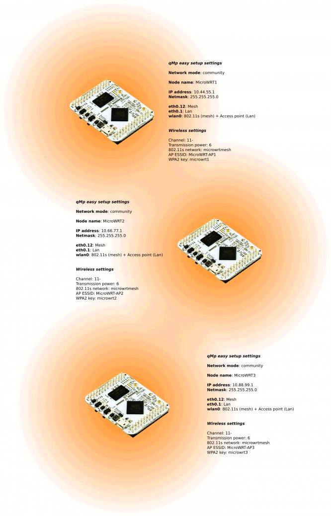
Settings summary
The following image summarizes the setting for the three nodes.
Configuring the nodes
This section covers the configuration of the first node (MicroWRT-1). The other two nodes are configured similarly, just changing the settings according to the previous section.
|
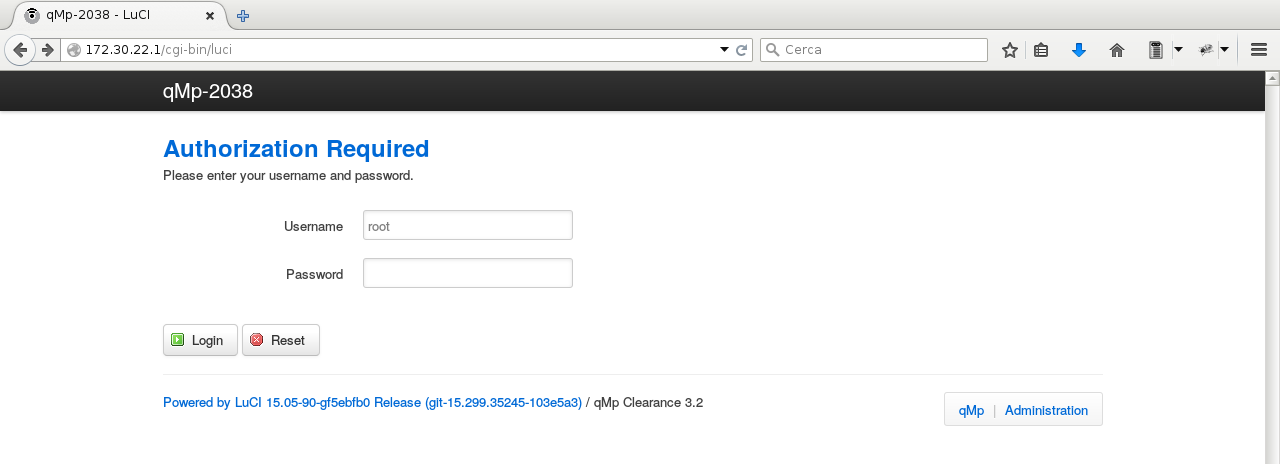
We first open the node's web interface at http://172.30.22.1 and use the default credentials to log in (see the Documentation page). |
|
|
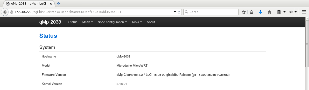
After logging in, the Status page is shown, displaying information about the node, the status of the network interfaces, the list of nodes in the mesh network, the associated wireless stations, etc. |
|
|
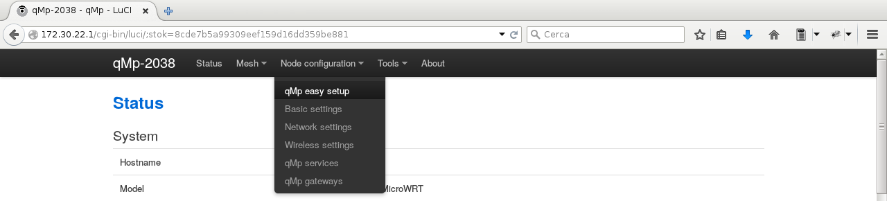
We browse the menu to go to the qMp easy setup page: |
|
|
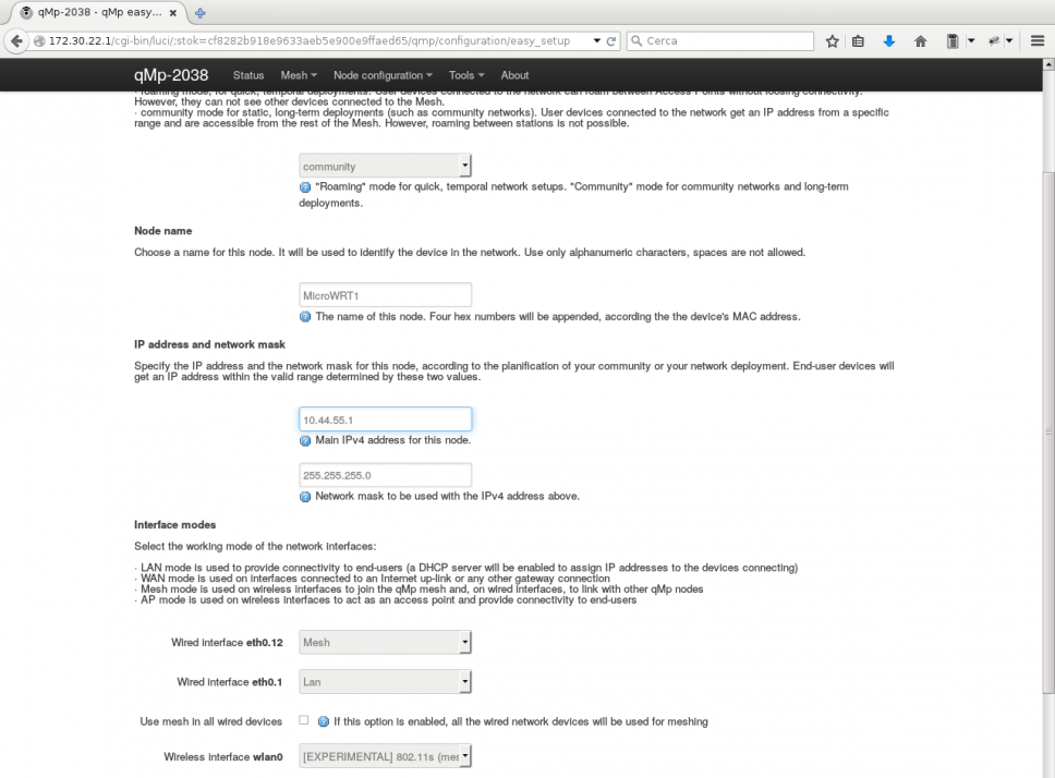
The settings from the previous section are used to configure the node on the qMp easy setup page: Network mode: community Click on Submit to save and apply the changes. It takes a few seconds. |
|
|
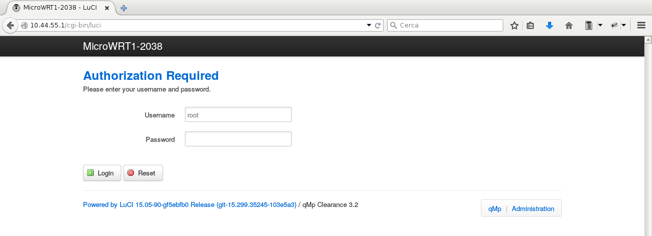
The IP address of the device has changed, so we disconnect the computer from it (either Ethernet or WiFi) and we connect back, to renew the IP address. We open the web interface again, now at http://10.44.55.1 . |
|
|
We browse the menu to go to the Wireless settings page: |
|
|
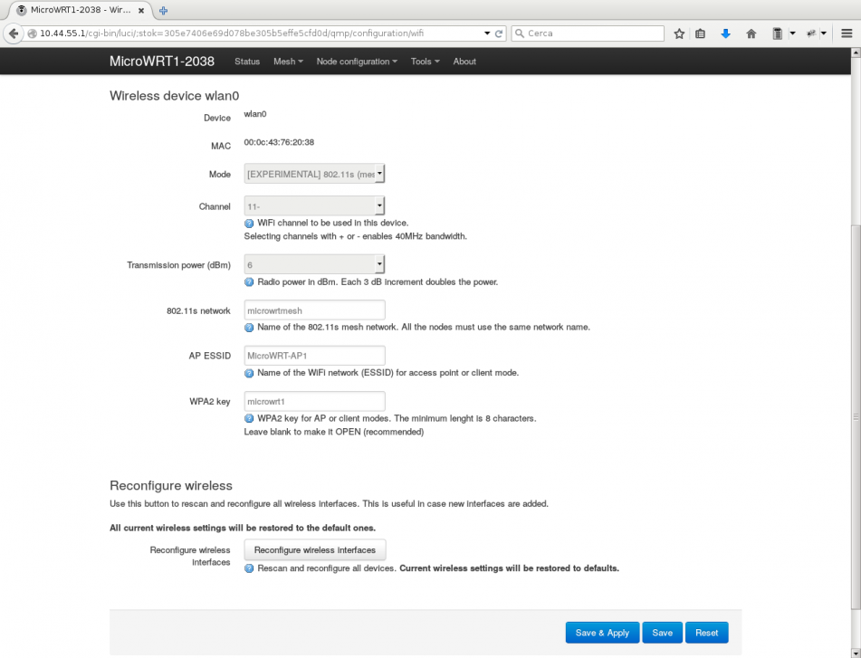
The settings from the previous section are used to configure the node on the Wireless serttings page: Channel: 11- With this, we configure the wireless channel on which the radio device operates and the transmission power. The 802.11s network string identifies the mesh network and must be used by all the nodes. Finally, the AP will generate the MicroWRT-AP1 network and, to connect other devices to it, the required password will be microwrt1. |
|

Checking the deployment network graph
Once the three nodes are flashed and configured, if they are deployed within a reasonable distance (e.g. from a few to tens of meters, depending on the environment), they will all connect to each other, creating the mesh network.
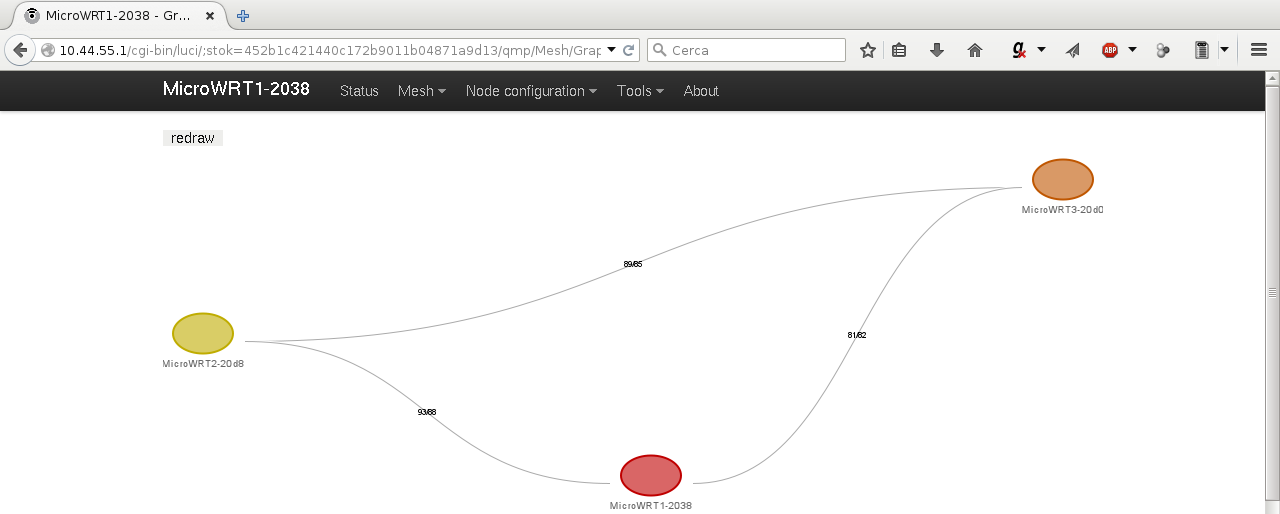 You can check the mesh network graph by clicking on qMp => Mesh => Graph . The page shows the nodes currently in the mesh network, the links between them and the quality of the connection between them.
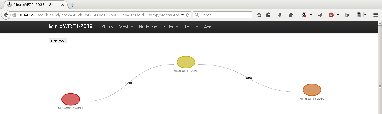 Finally, if the connectivity between the nodes changes, this is reflected on the graph. For example, nodes MicroWRT1 and MicroWRT3 are moved away, keeping MicroWRT2 in the middle. At some point, the two nodes are no longer connected between them, but they are still connected via MicroWRT2. The BMX6 routing protocol detects it and now, the two nodes on the edges can exchange data using the one in the middle as an intermediate node.
The second part of this tutorial, titled Experimenting with the Microduino MicroWRT Core (II) explains how to connect a Microduino module to the MicroWRT Core, read a value from a sensor and send it to all the devices of the mesh using the SMS plugin of the BMX6 routing protocol.
Experimenting with the Microduino MicroWRT Core (I)
We are experimenting with three MicroWRT Core boards that Jason from Microduino™ kindly sent us some days ago.
The MicroWRT is a small and cheap development board based on the MediaTek MT7620A SoC (which integrates Ethernet networking and 2.4 GHz WiFi 2T2R), with 64 MB of RAM and 16 MB of flash storage. It is fully supported by the currently latest OpenWrt 15.05 Chaos Calmer release and, since recently, by the qMp 3.2 Clearance stable release.
The device consists of a board with the SoC, a µUSB port, two buttons, two antenna connectors and 52 accessible pins. These pins can be used to stack several boards that provide diverse functionalities (Ethernet, USB, mPCI-E, etc.) and to even to a series of Microduino™ board (which are Arduino-compatible).
Its powerful CPU, its small size, the number of extension boards that can be attached to the MicroWRT Core and its interaction capabilities with the Microduino™ range of boards make it a very interesting option to build a mesh network with sensors, actuators, etc. with up to several Mb/s of throughput.
This article covers the installation and configuration of qMp in three MicroWRT Core devices that create a small mesh and exchange data from a sensor between them.
Installing qMp
The MicroWRT Core is shipped with PandoraBox, a sort of Chinese customisation of OpenWrt -anyway, OpenWrt after all-. Therefore, flashing qMp or upgrading to a newer OpenWrt version is very easy and can be done using the node's LuCI web interface.
First, download the appropriate qMp precompiled binary firmware from the Download page, or compile it with your preferred options. At the time of writing this page, the latest stable qMp firmware for this device is available here.
Connect the device to your computer, either via Ethernet or WiFi. The factory firmware puts the wireless interface in access point and creates up an open wireless network named PandoraBox_XXXX which you can use to flash the device, but it is recommended to do it via cable. Open the device's web interface with your browser and go to the System menu => Backup / Flash firmware. Use the form to select the qMp firmware file (make sure you don't keep the previous settings) and upload it to the device. Proceed flashing the device and, in a few minutes, the device will be flashed and configured with the default settings.
Default settings
After flashing qMp, once the autoconfiguration process finishes, the device is configured as follows:
- Ethernet port: LAN (switch port 4, eth0.1)
- Wireless: 802.11s mesh + AP LAN (channel 1)
- IPv4 address: 172.30.22.1/16
You can reach your device via Ethernet or via WiFi (the default network name is "qMp-AP"). The web interface is at http://172.30.22.1 or http://admin.qmp (you can check the default username and password on the Documentation page).
If you flash two or more devices, thanks to the autoconfiguration process, they will start meshing automatically.
Configuring a small mesh network with three nodes
In this section we are going to configure three MicroWRT nodes to show an example on how to create a small wireless mesh network with three devices connected between them via WiFi.
Settings summary
The following image summarizes the setting for the three nodes.
Configuring the nodes
This section covers the configuration of the first node (MicroWRT-1). The other two nodes are configured similarly, just changing the settings according to the previous section.
|
We first open the node's web interface at http://172.30.22.1 and use the default credentials to log in (see the Documentation page). |
|
|
After logging in, the Status page is shown, displaying information about the node, the status of the network interfaces, the list of nodes in the mesh network, the associated wireless stations, etc. |
|
|
We browse the menu to go to the qMp easy setup page: |
|
|
The settings from the previous section are used to configure the node on the qMp easy setup page: Network mode: community Click on Submit to save and apply the changes. It takes a few seconds. |
|
|
The IP address of the device has changed, so we disconnect the computer from it (either Ethernet or WiFi) and we connect back, to renew the IP address. We open the web interface again, now at http://10.44.55.1 . |
|
|
We browse the menu to go to the Wireless settings page: |
|
|
The settings from the previous section are used to configure the node on the Wireless serttings page: Channel: 11- With this, we configure the wireless channel on which the radio device operates and the transmission power. The 802.11s network string identifies the mesh network and must be used by all the nodes. Finally, the AP will generate the MicroWRT-AP1 network and, to connect other devices to it, the required password will be microwrt1. |
|
Checking the deployment network graph
Once the three nodes are flashed and configured, if they are deployed within a reasonable distance (e.g. from a few to tens of meters, depending on the environment), they will all connect to each other, creating the mesh network.
You can check the mesh network graph by clicking on qMp => Mesh => Graph . The page shows the nodes currently in the mesh network, the links between them and the quality of the connection between them.
Finally, if the connectivity between the nodes changes, this is reflected on the graph. For example, nodes MicroWRT1 and MicroWRT3 are moved away, keeping MicroWRT2 in the middle. At some point, the two nodes are no longer connected between them, but they are still connected via MicroWRT2. The BMX6 routing protocol detects it and now, the two nodes on the edges can exchange data using the one in the middle as an intermediate node.
The second part of this tutorial, titled Experimenting with the Microduino MicroWRT Core (II) explains how to connect a Microduino module to the MicroWRT Core, read a value from a sensor and send it to all the devices of the mesh using the SMS plugin of the BMX6 routing protocol.